Right-Angle Mount Belt-Driven Stepper Linear Actuators: Maximizing Usable Space in Compact Indexing Machines
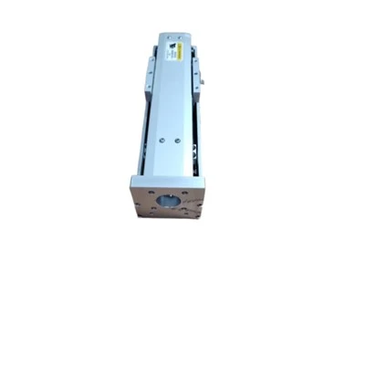
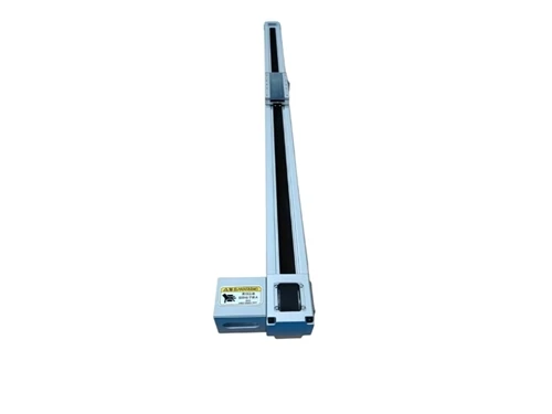
- This right-angle belt-driven linear actuator offsets the stepper motor parallel to the travel axis by wrapped timing belt transmission and removes motor overhang outside machine frames. It integrates recirculating ball linear guides inside the extrusion to cut down section height, intended for indexing dials, confined pick-and-place cells and slit-space stations where conventional inline motor mounting cannot fit.
- Inline stepper mounting places the motor axially along the travel direction. This arrangement adds 85–140 mm of outward protrusion depending on motor frame size. Many compact indexing platforms built for relay assembly reserve less than 60 mm of peripheral clearance around the working envelope. Under this constraint, standard inline assemblies interfere with guarding, dial fixtures and adjacent vision stations.
- This spatial limit is common in low-profile turnkey lines built for magnetic relay stacking, contact riveting and inline electrical testing. For these layouts, the available footprint restricts actuator selection to structures that separate the motor from the linear carriage axis.

Full Technical Comparison Table
Product drawing


| Parameter | Inline Stepper Belt Actuator | Right-Angle Belt-Driven Stepper Actuator | Selection Note |
|---|---|---|---|
| Mounting Configuration | Motor mounted axially along travel axis | Motor offset parallel to travel axis via 90° timing belt wrap | Choose right-angle version when lateral clearance is limited |
| Repeatability | ±0.02 mm | ±0.02 mm | Same positioning accuracy for both structures |
| Max Continuous Thrust | 180 N | 165 N | Confirm payload and safety margin before selection |
| Peak Thrust | 260 N | 240 N | Check against short-stroke push requirements |
| Allowable Linear Speed | 1.2 m/s | 1.1 m/s | Match to required cycle time |
| Side Protrusion Beyond Extrusion | 90–140 mm | <18 mm | Right-angle design removes external motor overhang |
| Overall Assembly Height | Standard profile | 22% lower than externally mounted guide version | Preferred for low-profile machine frames |
| Guide Type | External recirculating ball guide | Embedded recirculating ball guide inside aluminum extrusion | Embedded guide reduces exposed rail height |
| Rated Static Moment Capacity | 32 N·m | 28 N·m | Verify moment load at both stroke ends |
| Backlash Under Rated Thrust | <0.03 mm | <0.03 mm | Suitable for repeatable pick-and-place motion |
| Motor Control | Open-loop or closed-loop stepper | Closed-loop stepper with 1000-line incremental encoder | Closed-loop unit is recommended for short-stroke high-cycle transfer |
| Holding Torque at 150 rpm | 78% of rated | 85% of rated | Higher low-speed torque supports tight station operation |
| Step-Loss Suppression | Not guaranteed under low-speed load | Closed-loop feedback suppresses step loss | Required for thin-contact relay handling |
| Stall Detection | Optional | Standard, triggers immediate motion stop | Protects fixtures and workpieces from collision |
| Belt Preload Adjustment | Screw-type tensioner | Screw-type fixed preload adjuster | Reserve access space for periodic tension check |
| Maintenance Interval | 8,000 operating hours | 7,200 operating hours | Follow scheduled inspection based on duty cycle |
| Relative CAPEX | Baseline | +12% | Balance layout requirement against equipment cost |
| Typical Stroke Range | 100–1,200 mm | 100–1,000 mm | Confirm maximum stroke with machine layout |
| Payload Range | 1–15 kg | 1–12 kg | Include fixture weight in payload calculation |
| Recommended Duty Cycle | ≤80% continuous | ≤75% continuous | Avoid continuous overload operation |
| Environmental Protection | IP20 standard | IP20 standard | Add enclosure if dust or splash protection is required |
| Operating Temperature | 0–40 °C | 0–40 °C | Confirm workshop temperature before acceptance |
| Compatible Motor Brands | Panasonic, Omron, Inovance | Panasonic, Omron, Inovance | Spare parts follow mainstream mounting footprints |
| Spare Part Cross-Reference | Available on request | Available on request | Provide model list during RFQ |
| Changeover Time for Tooling | 30–45 min | 25–40 min | Modular fixture interface reduces changeover effort |
| FAT Acceptance Cpk | ≥1.67 at rated payload | ≥1.67 at rated payload | Required during positioning repeatability test |
| SAT Endurance Test | 100,000 cycles | 120,000 cycles without belt preload adjustment | Verify long-cycle stability before site handover |
| Target Applications | General pick-and-place, long-stroke transfer | Compact indexing dials, slit-space stations, confined PPU cells | Match structure to actual workstation envelope |
| Not Recommended For | Narrow-frame machines with limited lateral clearance | High-force press-fit tasks, >20 kg payload | Use servo electric cylinder for high-force press-fit |