Building 3-Axis Cartesian Gantries with Standardized Linear Modules: Step-by-Step Engineering Calculation
A 3-axis Cartesian gantry uses orthogonal linear modules to deliver X/Y/Z linear positioning. Cantilever Z axes generate pitch, yaw and roll dynamic moments during acceleration. This article provides quantitative calculation workflows for motor torque, extrusion beam deflection and drag chain routing for spans exceeding 1000 mm.
Dynamic Moments: Pitch, Yaw, Roll on Cantilever Z
Dynamic moment arises from payload and moving mass under acceleration.
- Pitch moment: \(M_p = m_{total} \cdot a_x \cdot L_z\)
- Yaw moment: \(M_y = m_{total} \cdot a_y \cdot L_z\)
- Roll moment: \(M_r = F_{friction} \cdot r_{guide}\)
- \(m_{total}\) = moving mass (Z module + end effector + workpiece); \(L_z\) = cantilever overhang length.
- All moment values must sit within linear module allowable moment rating at maximum acceleration.
Motor Torque Calculations (Inertia, Lead, Friction)
Total required torque:
- \(\tau_{total} = \tau_{inertia}+\tau_{friction}+\tau_{axial}\)
- \(\tau_{inertia}=I_{total}\cdot\alpha\)
- \(I_{total}\) includes motor rotor inertia, ball screw inertia and reflected payload inertia.
- Safety factor ≥1.5 for continuous duty; ≥2.0 for high-cycle pick-and-place.
- Verify speed-torque curve before motor selection.
Extrusion Beam Deflection over 1000mm+ Spans
Max static deflection formula for simply supported beam:
- \(\delta_{max}=\frac{F\cdot L^3}{48\cdot E\cdot I}\) \(\delta_{max}=\frac{F\cdot L^3}{48\cdot E\cdot I}\) E = modulus of aluminum extrusion; I = area moment of inertia.
- Limit deflection ≤0.1 mm at full payload for precision assembly applications.
- Dual parallel linear modules reduce deflection by increasing section inertia.
Drag Chain Layout Preventing EMI & Cable Fatigue
Minimum bend radius ≥7× cable outer diameter
- Separate power cables and encoder cables by ≥100 mm to reduce EMI coupling
- Fix cable strain relief at both moving and stationary ends
- Avoid cable twisting during full stroke movement
- Schedule drag chain inspection every 8,000 operating hours
Engineering Selection Checklist
- Calculate pitch/yaw/roll moments at peak acceleration
- Match motor inertia ratio 0.2–5:1
- Compute beam deflection at full payload and maximum span
- Select drag chain bend radius and cable separation layout
- Validate Cpk ≥1.33 for positioning repeatability under FAT
-
Select drag chain bend radius and cable separation layout
-
Validate Cpk ≥1.33 for positioning repeatability under FAT
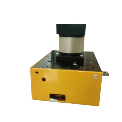
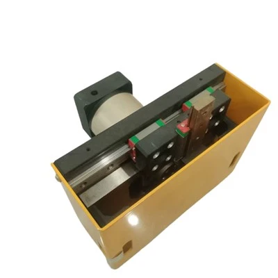
Why Choose Yangning Cartesian Manipulator Solutions
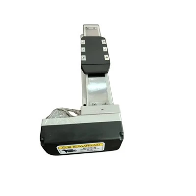
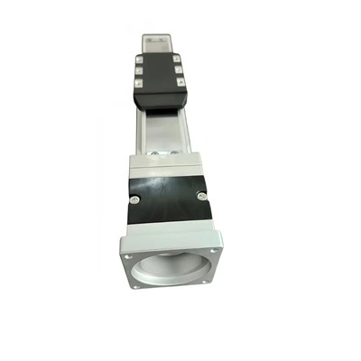
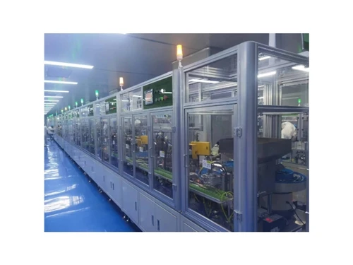
Yangning supplies standardized linear modules for custom PPU & Manipulators. Pre-calculated mechanical performance data reduces customer design cycle. Full FAT reports, dimension inspection records and cycle test data are delivered with each assembly.
Request Turnkey Line Cycle-Time Simulation for Your Part Drawings.
Linear Module Drive Type Comparison Table
| Parameter | Ball Screw Module | Belt Driven Module |
|---|---|---|
| Repeatability | ±0.005 mm | ±0.05 mm |
| Max Velocity | 0.8 m/s | 3.5 m/s |
| Maintenance Interval | 10,000 h | 5,000 h |
| Relative Capex | High | Medium |
| Allowable Dynamic Moment | High | Medium |
Download Detailed 3D CAD (.STEP) Models for Slide Table and Linear Module